
If you have ever wanted to control a single light fixture from three or more different locations—like the top, middle, and bottom of a large staircase—you will need to understand how a 4 way switch schematic diagram works. While standard single-pole switches are straightforward, multi-location setups require a bit more planning and precision. Honestly, once you grasp the flow of electricity through these circuits, wiring them becomes a highly manageable project.
Demystifying the 4-Way Switch Schematic Diagram

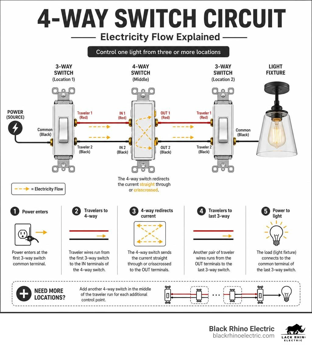
Quick answer: A 4-way switch schematic diagram shows how to wire one 4-way switch between two 3-way switches to control a light from three or more locations. Here is how the basic circuit works:
- Power enters at the first 3-way switch’s common terminal.
- Traveler wires (typically black and red) run from the first 3-way switch to the two IN terminals of the 4-way switch.
- The 4-way switch redirects the current — either straight through or crisscrossed — to its two OUT terminals.
- Another pair of traveler wires runs from the OUT terminals to the second 3-way switch.
- The load (light fixture) connects to the common terminal of the last 3-way switch.
Need more than three locations? Simply add another 4-way switch in the middle of the traveler run for each additional control point.
Here’s the thing — over 70% of residential multi-location lighting projects use 3-way and 4-way switch configurations, and roughly 60% of 4-way switch installations involve controlling lights from three or more spots. Yet incorrect wiring accounts for nearly 25% of reported faults in these circuits. That gap between how common these setups are and how often they go wrong is exactly why a clear, reliable schematic matters so much.
In this guide, you will find every major wiring configuration, NEC code requirements, troubleshooting steps, and smart home integration tips — all explained in plain language. If you need a refresher on the basics first, you can check out our guide on How to Wire a Light Switch. For a visual breakdown of the electrical path, you can also view this helpful How 4-way switches work — an animation.
What is a 4-Way Switch and How Does It Work?
To understand a 4-way switch, we first have to look at how it differs from a 3-way switch. A 3-way switch has three screw terminals (one common and two travelers) and acts as a single-pole, double-throw switch. It directs current to one of two traveler wires.
A 4-way switch, on the other hand, has four terminals and no “common” terminal. It sits comfortably in the middle of the circuit, acting as a toggle-controlled signal redirector. Inside the switch, the electrical connections either pass straight through or crisscross. This changing of the guard is what allows any switch in the chain to independently interrupt or complete the circuit.
According to residential electrical data, about 60% of these configurations are installed in large open-concept living rooms, long hallways, or multi-level staircases. If you want to dive deeper into the physical installation process, this guide on How to Wire a 4 Way Switch (with Pictures) – wikiHow offers an excellent step-by-step breakdown.
Key Components of a 4-Way Switch Schematic Diagram
When you look at a 4 way switch schematic diagram, identifying the terminals is half the battle. A standard 4-way switch features:
- Two pairs of traveler terminals: These are typically color-coded. Many manufacturers use two brass screws for the input travelers (IN) and two black/dark screws for the output travelers (OUT).
- A green grounding screw: Essential for safety and bonding to your home’s grounding system.
Let’s talk wire colors. In standard non-metallic (NM) cable runs, you will use 3-wire cable (which contains black, red, white, and a bare copper ground).
- Black and Red wires are typically used as travelers.
- White wires are traditionally neutrals, but in some older multi-location switch loops, they may be used as hot travelers. If a white wire is used as a traveler or hot leg, code requires you to wrap it with black or red electrical tape at both ends to identify it clearly.
For a clean visual aid on terminal layouts, you can reference this Simple 4 Way Switch Wiring Diagram: Easy Guide to keep your connections organized.
Step-by-Step Wiring Configurations and Methods
Before pulling any wires through your walls, planning the physical layout is crucial. If you are in the middle of a home renovation here in Ogden or Layton, keeping an Electrical Rough-In Checklist handy will save you from major headaches down the line.
Standard 4-Way Switch Schematic Diagram Configurations
There are several ways to route power and travelers through a 4-way circuit. The layout you choose depends on where your power source enters and where the light fixture sits.
| Wiring Method | Difficulty | Best For | Code Compliance (Neutral at Switch) |
|---|---|---|---|
| Basic Method | Easy | Power enters Switch 1, ends at Light | Yes (with 3-wire run) |
| Dead-End Method | Advanced | Power and Light at the same physical box | Requires careful cable planning |
| Light-Fed Method | Hard | Power enters at the light fixture box | Harder to meet modern code |
- The Basic Method: This is the gold standard. Power enters the first 3-way switch box, travelers run through the 4-way switch box to the second 3-way switch box, and the switch leg goes directly to the light. It is clean, easy to understand, and highly recommended for DIYers.
- The Dead-End Configuration: Used when power and the light switch leg are in the same box, but you need to run switches out to other locations without looping the neutral all the way back.
- The Two-Wire Traveler Method: An alternative setup that uses fewer conductors but requires precise parallel routing to avoid electromagnetic impedance issues.
For an exhaustive look at all eight professional wiring variations, check out Mastering 4 Way Switch Circuits: The Definitive Guide.
NEC 404.2(C) Neutral Wire Requirements
You know what? Electrical codes aren’t just there to make your life difficult—they keep your home safe. The National Electrical Code (NEC) 404.2(C) rule requires a neutral wire at almost all switch locations. This rule was introduced primarily because modern smart switches and occupancy sensors require a small amount of continuous standby power, which they get via the neutral wire.
When wiring a 4-way switch circuit under modern codes:
- You must ensure a neutral wire (usually white) is present in each switch box, even if the mechanical switch itself does not connect to it.
- This often means running 3-wire NM cable (which has an extra conductor) or 4-wire cable between your switch boxes.
To see compliant diagrams that utilize 3-wire NM cable to satisfy this code, review How to Wire 4-Way Switches + Diagrams.
Troubleshooting, Smart Integration, and Professional Safety
Working with electricity requires absolute respect for safety. Whether you are wiring a simple light or setting up a Dedicated Circuit for a heavy appliance, always turn off the breaker first and verify the lines are dead with a reliable, non-contact voltage tester.
Troubleshooting Common Multi-Location Wiring Issues
If you flip your new switches and nothing happens—or the light only works when certain switches are in a specific position—don’t panic. Incorrect wiring causes 25% of all faults in these circuits. Here is how to systematically find the issue:
- Turn off the power at the breaker panel.
- Pull the switches out of their boxes without disconnecting the wires yet.
- Check for loose connections. A single loose traveler wire will break the entire circuit chain.
- Identify traveler pairs. Use a multimeter to test continuity. Ensure that travelers coming from the first 3-way switch connect to the input (IN) terminals of the 4-way, and the travelers going to the next switch connect to the output (OUT) terminals.
- Never mix IN and OUT travelers. Connecting one incoming traveler to an OUT terminal and vice versa is the most common installation error.
If you are dealing with long wire runs across large homes in Kaysville or Bountiful, you may also want to learn How to Calculate Voltage Drop to ensure your fixtures receive consistent power. For a downloadable reference guide to keep on your phone, see this 4-Way Switch Wiring Diagram PDF | Easy Installation Guide.
Integrating Smart Home Systems and Dimmers
Want to add dimming or voice control to your multi-location setup? It is entirely possible, but smart switches handle 4-way configurations differently than mechanical ones.
Typically, you will install the primary smart switch at the box where power enters. The other switch locations will use specialized “auxiliary” or “add-on” switches that send digital signals to the master switch rather than physically routing the 120V load.
For example, when using popular Z-Wave or Zigbee setups, you may need to rewire the middle 4-way box using a modified wiring method. You can find a detailed smart home wiring layout in the 4-Way Wiring Solution A – DIY Smart Home Guy guide. If your project also involves multi-functional fixtures, you might find our guide on How to Wire a Ceiling Fan helpful.
Whether you are upgrading your home in Ogden with a new EV charger, installing a hot tub in North Ogden, or tackling a complex whole-house rewiring project in Roy, our team at Black Rhino Electric is here to make your project seamless and safe.
If you are ready to upgrade your home’s electrical system or need professional assistance with complex wiring, don’t hesitate to Request a Free Quote online today to get started with Weber County’s trusted electrical experts.