Feeling a bit lost staring at a sheet full of strange symbols and crisscrossing lines? Learning how to read electrical blueprints can seem daunting, but it's the single most important document for any electrical project. Think of it as the detailed instruction manual for a building's entire nervous system, ensuring every switch, outlet, and fixture is installed safely and correctly.
Your First Look at Electrical Blueprints
So, where do you begin when you’re trying to figure out how to read electrical blueprints? Here’s the thing: the key is to start with the big-picture view before getting lost in the weeds. A methodical approach turns that confusing sheet of paper into a clear roadmap for any electrical project.
Start with the Blueprint's ID Card: The Title Block
Before you even try to decipher a single symbol, your first stop should always be the title block. This is the blueprint's identification card, usually parked in the bottom right-hand corner of the drawing. It contains all the critical administrative information about the project.
Skipping this step is a common mistake that can lead to major confusion later. The title block tells you exactly what you're looking at.
Here’s what you'll typically find there:
- Project Name and Address: This confirms you have the right set of plans for the right building. Simple, but critical.
- Architect/Engineer Information: Identifies the professionals who designed the system.
- Sheet Title: Tells you the specific purpose of that page (e.g., "First Floor Electrical Plan," "Panel Schedule").
- Scale: Notes the drawing's scale, like 1/4" = 1'-0", which tells you how measurements on paper translate to real-world dimensions.
- Revision Dates: This is crucial. It shows a history of changes, ensuring you are working from the most current version of the plan.
Your Decoder Ring: The Legend
Once you've oriented yourself with the title block, the next essential thing to find is the legend, also known as the symbol list or key. This is your decoder ring for everything else on the page. It’s a visual dictionary, matching each symbol on the drawing to a specific electrical component.
Trying to read a blueprint without first studying the legend is like trying to read a book in a language you don't know. It's the absolute key to understanding what you're seeing.
The legend eliminates any guesswork. While many symbols are standardized, architects and engineers sometimes use variations. For that specific project, the legend is the ultimate source of truth, period.
Understanding the Different Types of Drawings
An electrical plan isn't just one drawing; it's usually a set of different views that work together to provide a complete picture. Getting familiar with the main types will help you know where to look for specific information.
| Drawing Type | Purpose and What It Shows |
|---|---|
| Floor Plans | This is the main drawing you'll work with. It's a top-down view showing the physical location of all electrical components—outlets, switches, lights, etc.—laid over the architectural floor plan. |
| Schematic Diagrams | These drawings focus on how components are connected electrically, not where they are physically located. They're more abstract, like a subway map, showing the logic of the circuits. |
| One-Line Diagrams | A simplified version of a schematic, this drawing uses single lines to represent the flow of power from the utility source through major components like transformers and panelboards. It's a high-level overview. |
Understanding these basic components—the title block, the legend, and the different drawing types—lays the groundwork for everything else. For homeowners undertaking significant work, such as with a new construction electrician, this foundational knowledge empowers you to have more productive conversations and better understand the scope of your project. With this base, you’re ready to dive into the language of symbols and lines.
Decoding the Language of Lines and Symbols
Alright, you’re oriented with the layout. Now comes the part that usually intimidates people: the symbols and lines. Honestly, it’s less like rocket science and more like learning a new, visual alphabet. Once you can recognize a few key shapes, the whole plan starts to click into place.
Think of it this way: every symbol is a noun (an outlet, a switch, a light), and every line is a verb (showing how they all connect). Your job is to read these simple "sentences" to understand the full story of the electrical system.
The Most Common Symbols You Will Encounter
Every blueprint worth its salt will have a legend, which we covered earlier. But let me walk you through the symbols you’ll see again and again on almost any residential project. Knowing these by heart will speed things up immensely.
Here are the non-negotiables:
- Outlets (Receptacles): That circle with two little parallel lines is your standard wall outlet. You’ll see variations, too. A circle with "GFCI" means it's a Ground Fault Circuit Interrupter outlet—the kind required near water. See "WP"? That means it’s a weatherproof outlet for outside.
- Switches: A simple "S" is the basic symbol for a switch. If you see an "S₃", that’s a three-way switch, used to control one light from two different spots, like at the top and bottom of the stairs.
- Lighting Fixtures: This is where you’ll see the most variety. A plain circle is often a basic ceiling light. A rectangle with a circle inside might be a recessed can light. You’ll also spot specific symbols for ceiling fans and wall sconces. Getting these fixtures installed correctly is a huge part of a successful project, which we dive into in our guide to professional lighting installation.
Once you get these core symbols down, you can glance at a floor plan and immediately see where power is, where the lights are, and what controls them.
Interpreting the Lines That Connect Everything
The symbols are the destinations, but the lines are the roadmap showing how electricity gets there. Different line types tell you how the wiring is run through the structure, and it’s a simple but vital distinction.
You know what? This is where a lot of misinterpretations happen. Reading a line type wrong can lead to serious rework—like having to open up a brand-new wall because the wiring was run incorrectly.
Here’s a quick breakdown:
- Solid Lines: These usually represent wiring that's exposed or run in a visible conduit, not hidden inside a wall.
- Dashed or Dotted Lines: This is what you’ll see most often on residential plans. It means the wiring is concealed within walls, floors, or ceilings.
- Curved or Arced Lines: These are often called "switch legs." They show the connection from a specific switch to the light fixture it controls.
Getting this part right isn’t just about making things look neat; it’s about safety and efficiency. A poorly read plan can lead to dangerous mistakes. For instance, misinterpreting the symbols for weatherproof (WP) or underground (UG) wiring can create serious hazards down the road.
Meticulous attention here is critical. The National Fire Protection Association (NFPA) reports around 42,000 home fires each year are caused by electrical malfunctions. Many of these trace back to installation errors that could have been prevented by reading the plans correctly. In fact, electrical blueprint errors contribute to nearly 20% of all electrical construction rework—a massive, costly problem.
Common Residential Electrical Blueprint Symbols
To make this practical, I've put together a quick-reference table with the symbols you'll see most often. Keep this handy when you're looking at your own plans; it’ll help you build that recognition muscle fast.
| Symbol | Description | Common Use Case |
|---|---|---|
| Duplex Receptacle | The standard wall outlet found in most rooms for plugging in lamps, chargers, and appliances. | |
| GFCI Receptacle | A safety outlet that quickly shuts off power to prevent shock. Required in kitchens, bathrooms, and outdoors. | |
| Single-Pole Switch | The most common light switch, used to control a light (or group of lights) from one location. | |
| Three-Way Switch | Used in pairs to control a single fixture from two different spots, like a hallway or large room. | |
| Ceiling Light Fixture | Represents a standard surface-mounted light on the ceiling, often in bedrooms or closets. | |
| Recessed/Can Light | A light fixture installed into a hollow opening in a ceiling, providing a clean, modern look. | |
| Ceiling Fan | A symbol for a ceiling-mounted fan, often shown with a light kit symbol included if applicable. |
Familiarizing yourself with these foundational elements gives you the vocabulary to understand the entire blueprint. Next up, we’ll connect these individual pieces by tracing their paths back to the electrical panel, which is where the whole system comes to life.
Tracing Circuits from Panel to Plug
Knowing the symbols is one thing, but the real magic in reading electrical blueprints is seeing how they all connect. It's about tracing the pathways, following the flow of power from the source all the way to the final plug.
Honestly, it feels a bit like being a detective. You're following clues on the page to map out the home's entire electrical nervous system. This is where the static drawing comes alive.
Starting at the Heart: The Electrical Panel Schedule
Every single circuit in your home starts its journey at the electrical panel. So, that's where we'll start, too. On any good set of blueprints, you’ll find the panel schedule—a detailed table that acts as the panel's directory. It is absolutely essential.
Think of the panel schedule as the "Table of Contents" for your electrical system. It lists every circuit breaker and tells you exactly what each one controls.
A typical panel schedule will show you:
- Circuit Number: The unique ID for each breaker (e.g., 1, 2, 3…).
- Description of Load: What that circuit powers, like "Kitchen Counter Outlets," "Master Bedroom Lights," or "Dishwasher."
- Breaker Size: The amperage rating, like 15A or 20A. This is critical for safety.
- Voltage and Phase: More technical details about the power supply.
With this schedule, you can immediately see that circuit #5 is a 20-amp breaker dedicated solely to the kitchen countertop outlets. No guesswork needed.
Following the Path: Homeruns and Circuit Numbers
Okay, you know what each circuit does. Now it's time to find its path on the floor plan. Look for lines coming from the panel's location on the drawing. The main wire running from a specific breaker to the first device on its circuit is called a homerun.
On blueprints, a homerun is usually drawn as an arced line pointing back toward the panel, clearly marked with the circuit number from the schedule. This is the electrician's primary instruction. It tells them, "This is where circuit #5 begins."
This process is also critical for preventing overloads. Electricians carefully group outlets and lights to balance the load, making sure no single circuit is asked to do more than it can safely handle. You can learn more about why a well-organized panel matters in our guide to breakers and electrical panels.
This simple infographic visualizes the core process for understanding any electrical plan.
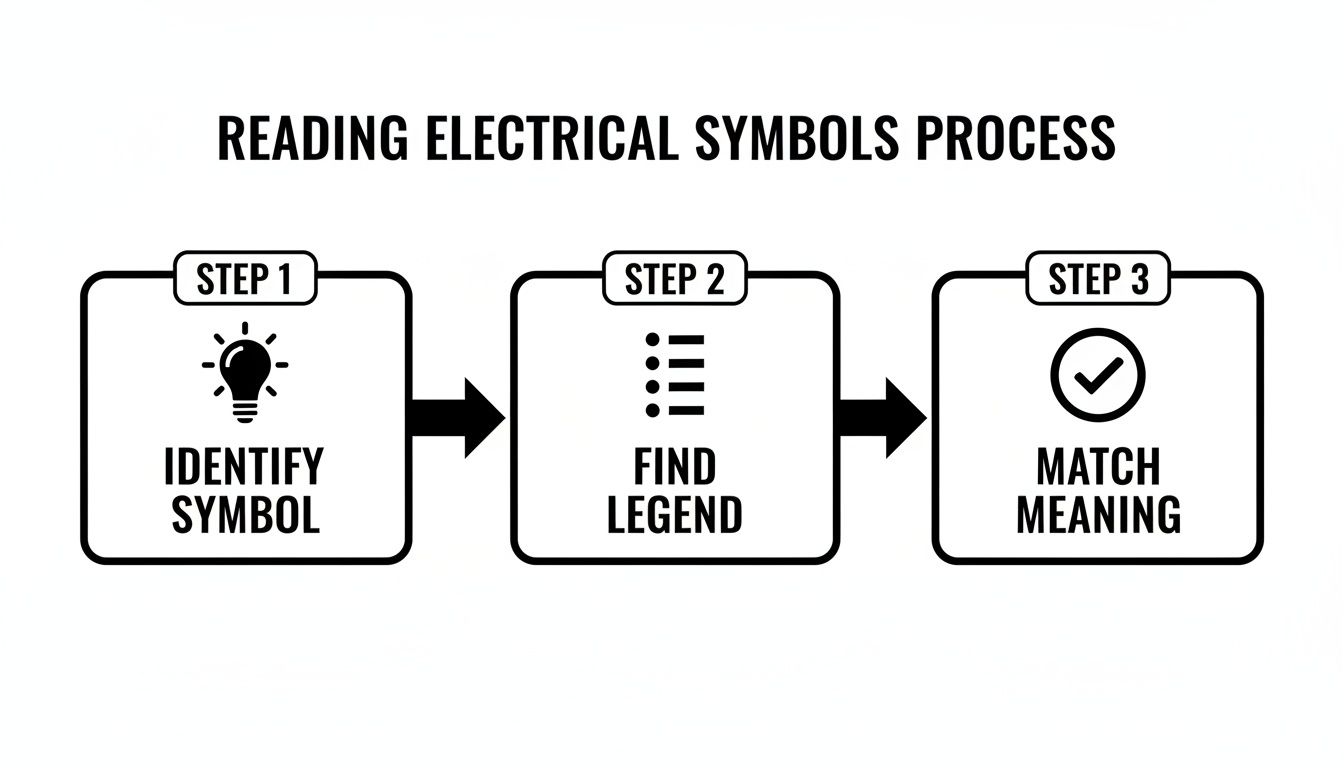
It really boils down to three simple actions: identify a symbol on the plan, find it in the legend, and match its meaning. That's the fundamental loop for getting it right.
Connecting the Dots From Device to Device
Once you’ve found the homerun and the first device, the rest is just connecting the dots. From that initial outlet or switch, you'll see lines extending to the next device on that same circuit, and so on.
Every device connected in this chain shares the same circuit number and is protected by the same breaker.
Pro Tip: Look for small tick marks across the wiring lines. These "hash marks" tell you the number of conductors inside that run of wire. For example, three marks usually means you have three wires (hot, neutral, and ground) running between those two devices.
Let's walk through that kitchen circuit (#5) from our panel schedule:
- First, you locate the electrical panel on the floor plan.
- Next, you find the arced line marked "#5" pointing to a GFCI outlet symbol on the kitchen counter. That's your homerun.
- From that first GFCI outlet, you just follow the line inside the wall to the next outlet symbol along the counter, then the next.
- You might then see the line jump up to the ceiling to connect a series of recessed lights, all part of the same circuit #5.
Just like that, you've traced an entire circuit and understand how multiple devices are grouped together. You'll also spot notes specifying wire gauges (like 12 AWG for a 20A circuit) and conduit sizes. These aren't minor details; they are vital instructions for a safe, code-compliant installation. This is how you see not just what is being installed, but why it's designed that way.
Putting It All Together: A Practical Checklist

Theory is one thing, but what do you do when a real set of plans is sitting on your desk? Let me explain. The secret to successfully reading any electrical blueprint isn't magic; it's having a systematic process.
Without a consistent approach, it's way too easy to miss a critical note or a misplaced outlet. Those small misses on paper can turn into costly rework or, worse, safety issues down the line. A structured review turns a confusing document into a clear, actionable plan.
Whether you're a homeowner staring at plans for a kitchen remodel or a contractor framing a new addition, this practical checklist will guide you through a thorough review, just like we do in the field.
Your Systematic Blueprint Review Process
Here’s the key: start big, then zoom in. Don’t get lost trying to trace a single circuit before you even understand the overall scope of the project. This top-down method ensures you catch everything in the right context.
This is the step-by-step process we use as professionals:
- Start at the Title Block and General Notes. Before you do anything else, confirm you have the correct and most recent set of plans. Check the project name, address, and especially the revision date. Then, read all the general notes. Seriously, read them. They often contain vital information about code requirements or project-specific standards you can't afford to miss.
- Study the Legend Thoroughly. Your next stop is the symbol legend. Don't just glance at it. Take a minute to really absorb the symbols for outlets, switches, and fixtures. This is your decoder ring for this specific set of plans.
- Analyze the Floor Plan Room by Room. Now you can begin your deep dive. Go through the plan one room at a time, tracing the circuits and identifying the location of every device. Mentally walk through how the space will function. Does the switch placement make sense? Are there enough outlets for how the room will be used?
- Cross-Reference with the Panel Schedule. As you analyze each room, constantly flip back to the panel schedule. If you see a circuit labeled "#7" in the bedroom, check the schedule to confirm it’s for the "Bedroom Outlets." This constant cross-referencing is what ensures everything aligns perfectly.
Key Items to Verify for Safety and Code Compliance
As you move through your review, keep your eyes peeled for specific details that are crucial for safety, functionality, and passing inspection. Spotting these things on paper is infinitely cheaper and easier than fixing them after the drywall is up.
Focus on these critical checkpoints:
- GFCI Protection: Verify that all outlets in required areas—like kitchens (within six feet of a sink), bathrooms, garages, and outdoor locations—are marked as GFCI (Ground Fault Circuit Interrupter). This is a non-negotiable safety code requirement.
- Adequate Outlet Spacing: Check that outlets are spaced according to code, which generally requires an outlet to be within reach every 12 feet along a wall. This is designed to prevent the unsafe use of extension cords.
- Dedicated Circuits: Look for notes indicating dedicated circuits for major appliances. Items like refrigerators, dishwashers, microwaves, and garbage disposals almost always require their own circuit to prevent overloads.
- Specialty Equipment Notes: Pay close attention to any special notes related to high-power equipment. This includes things like EV chargers, hot tubs, backup generators, or electric ranges, which have unique and demanding wiring requirements.
By following this systematic checklist, you transform the process of learning how to read electrical blueprints from a theoretical exercise into a powerful project management tool. It empowers you to spot potential issues before they become expensive problems.
The Real-World Impact of a Thorough Review
Mastering this skill has a massive impact on project efficiency. For instance, did you know that properly interpreting blueprints before work begins can slash project timelines by up to 30%? It allows electricians to spot potential issues, like inefficient wire routes or missing components, at the design stage.
Industry data shows that contractors trained in blueprint reading complete jobs 25-35% faster and with 40% fewer errors, directly improving project outcomes. You can learn more about these efficiency gains and how they are achieved.
Think of your blueprint review as the most important quality control step in the entire electrical installation process. A few hours spent carefully examining the plans can save you days of delays and thousands of dollars in change orders. It’s the difference between a smooth, on-budget project and one plagued by frustrating and costly surprises.
When to Call in the Pros
Learning how to read electrical blueprints is a fantastic skill. Honestly, it puts you in the driver's seat. You can understand the scope of your project, have smarter conversations with contractors, and even catch potential issues before they become real problems.
But let's be clear: knowing how to read the map is completely different from driving the route.
Executing the work shown on those plans is a whole other ballgame. It's a discipline that takes years of training, thousands of hours of hands-on work, and a deep, practical understanding of safety codes that are frankly mind-numbingly complex. The line between understanding a blueprint and safely wiring a house is wide and bright for a reason.
The Real Risks of DIY Electrical Work
This isn't like a little DIY drywall repair, where a mistake might leave a bump you have to sand down. A wiring error can have consequences that are immediate and severe—from electrical shocks and shorts that fry expensive appliances to, worst-case, a house fire.
The National Electrical Code (NEC) is a massive book that professional electricians spend their entire careers mastering. It exists specifically to prevent those worst-case scenarios.
When you try to translate a blueprint into a physical installation without that expertise, you're rolling the dice.
- Safety Hazards: It’s the little things that get you. Improper grounding, a connection that isn’t torqued just right, or using the wrong gauge of wire can create immediate fire or shock risks.
- Code Violations: Electrical work has to pass inspection. A failed inspection means rework, and that costs both time and money.
- Voided Insurance: If an electrical fire is traced back to unpermitted, non-professional work, you might find your homeowner's insurance claim denied. That’s a devastating financial hit.
What a Professional Brings to the Table
A licensed electrician does a lot more than just connect wires from point A to point B. We interpret the intent of the blueprint, making sure every circuit is properly balanced, every connection is rock-solid, and the entire system works safely and efficiently for years to come.
At Black Rhino Electric, our job is to turn those lines and symbols on paper into a safe, reliable, and fully compliant electrical system. We're the bridge between the design and a flawless, safe execution.
Whether you're looking at plans for a new panel upgrade, a full home rewire, or adding something like an EV charger, the work just has to be done right. There's no room for "good enough."
If you’ve gone over your blueprint and have a few questions, or if you’re ready to get your project moving, that’s the perfect time to bring in a professional. We make sure the job is done correctly from the very start, protecting your property and your family.
Frequently Asked Questions About Electrical Blueprints
Even with a good handle on the basics, a few specific questions always seem to pop up when people are learning how to read electrical blueprints. It's totally normal to have a few "wait, what about…" moments as you put all the pieces together.
To help clear things up, we've gathered answers to the questions our team hears most often from clients and contractors alike. Think of it as a quick reference guide for those nagging details that can make or break your understanding of a plan.
What Is the Difference Between a Schematic and a Blueprint?
This is a fantastic question because people use the terms interchangeably all the time, but they serve completely different purposes.
A blueprint, or what we usually call an electrical floor plan, shows you the physical location of everything. It's a map telling you exactly where on the walls and ceilings each outlet, switch, and light fixture will be installed.
A schematic diagram, on the other hand, is all about function, not location. It’s a simplified drawing that shows how components are electrically connected to form a circuit. Here’s a simple way to think about it:
- Blueprint (Floor Plan): A detailed road map showing the exact streets and addresses.
- Schematic Diagram: A subway map that shows how the stations connect, but not their precise geographical coordinates.
How Do I Know What Scale the Blueprint Is In?
The scale is critical—it's what translates the lines on the page to real-world dimensions. You can almost always find the scale listed in the title block, which is usually parked in the bottom-right corner of the drawing sheet.
For residential plans, you'll often see a ratio like 1/4" = 1'-0". This simply means every quarter-inch you measure on the paper equals one foot in the actual building. While the scale is great for estimating wire runs, always default to any specific measurements written directly on the plan. Those numbers take priority.
Are Electrical Symbols Universal?
This is a common trap for beginners. While many symbols are standardized by groups like the American National Standards Institute (ANSI), they are not entirely universal. Architects, engineers, and even different electrical firms might have their own slight variations or unique symbols for certain components.
This is precisely why the blueprint's legend is the most important part of the entire document. The legend is the ultimate source of truth for that specific project. Always, always check the legend first before making any assumptions about what a symbol means.
What Does a Dashed Line Mean on an Electrical Plan?
The type of line used on a blueprint tells a story about how the wire gets installed. Most of the time, a dashed or dotted line represents wiring that is concealed—run inside walls, above ceilings, or under floors. This is what you'll see on most interior residential plans.
On the other hand, a solid line often indicates wiring that's run in an exposed conduit or is otherwise visible after the job is done. But just like with symbols, conventions can vary. When in doubt, what's the golden rule? Check the plan's legend for the final word.
Even with a solid understanding of blueprints, turning those plans into a safe, reliable electrical system takes professional expertise. The team at Black Rhino Electric has the experience to interpret any plan and execute the work flawlessly, ensuring your project is up to code and built to last. For a professional review of your plans or to get your project started, give us a call at 385-396-7048 or request a free quote online today.