When a production line grinds to a halt, the pressure to find a solution can be overwhelming for any facility manager. Mastering electrical control panel troubleshooting is the key to minimizing costly downtime and ensuring the safety of your entire industrial operation. Honestly, having a systematic plan is the only way to turn a chaotic breakdown into a controlled repair.
When Your Control Panel Fails, Here’s What to Do First
Electrical control panel troubleshooting is one of the most critical skills in any industrial facility — and when something goes wrong, every minute of downtime costs real money. Whether you’re staring at a tripped breaker, a silent PLC, or a motor that won’t start, knowing where to look first makes all the difference.

Here’s the quick answer for anyone who needs it right now:
Step-by-step electrical control panel troubleshooting:
- Ensure safety first — follow Lockout/Tagout (LOTO) procedures and wear proper PPE before touching anything
- Gather information — talk to operators, note error codes, and document what was happening when the fault occurred
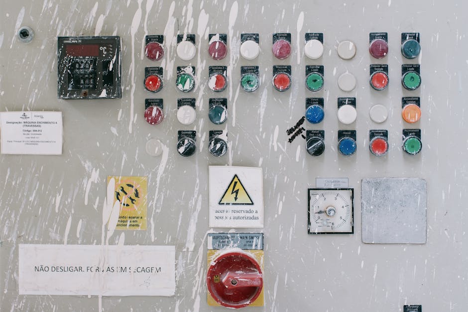
- Perform a visual inspection — look for burn marks, tripped breakers, blown fuses, and loose wiring
- Verify all power sources — use a multimeter to confirm voltage levels at incoming supply, control transformer, and 24VDC rails
- Isolate the fault — use schematics to narrow the problem to a specific subcircuit, component, or field device
- Repair and verify — fix the confirmed fault, then test all functions through a full operating cycle before returning to production
Here’s the thing: over 80% of automation faults originate in field devices, wiring, or power supplies — not the PLC itself. That means most panel failures are traceable, fixable, and preventable with the right approach.
Industrial control panels are complex systems. They distribute power, run motor controls, process signals from sensors, and execute logic from PLCs and HMIs — all at the same time. When one part fails, the symptoms can show up somewhere completely different. That’s what makes a systematic troubleshooting process so important. Jumping to conclusions and swapping parts at random wastes time and money. One real-world example says it all: a technician spent four hours randomly checking components before a systematic approach found a loose connection in just 15 minutes.
The sections below walk through every layer of control panel troubleshooting — from safety and tools to PLCs, motors, grounding, and preventive maintenance — so you can work through any failure with confidence.

A Systematic Approach to Electrical Control Panel Troubleshooting
When you face a dead machine, the “shotgun approach”—replacing parts until it works—is your worst enemy. It’s expensive, and you might never actually find the root cause. Instead, we use a medical-style diagnosis: look at the symptoms, check the history, and isolate the “organ system” that is failing.

The Diagnostic Process
You know what? Most experts agree that the best way to learn is by following a rigid structure. Let me explain the logic behind a professional-grade troubleshooting session:
| Symptom | Potential Root Cause | Diagnostic Action |
|---|---|---|
| Total Power Loss | Tripped Main Breaker or Blown Primary Fuse | Verify incoming line voltage with multimeter |
| Intermittent Operation | Loose Terminations or Electrical Noise | Perform “tug test” on wires; check shielding |
| PLC Input Not Triggering | Failed Field Sensor or Broken Wire | Test sensor with metal target; check 24VDC loop |
| Motor Overload Trip | Current Imbalance or Bearing Friction | Measure amperage on all three phases |
| Burning Odor | Overheated Component or Short Circuit | Immediate LOTO and visual/thermal inspection |
The key is to investigate the simplest potential problem first. Don’t assume the PLC program has “corrupted itself” (it almost never does). Instead, check if someone accidentally hit an E-stop or if a 24VDC power supply has failed. For more complex issues, you can learn more about our troubleshooting electrician services to see how we handle these high-pressure situations.
Essential Safety Protocols and Diagnostic Tools
Safety isn’t just a suggestion; it’s a survival requirement. Before you even open the panel door, you must be wearing the correct Personal Protective Equipment (PPE) as dictated by NFPA 70E standards. This often includes arc-rated clothing, insulated gloves, and safety glasses.
Critical Safety Steps:
- Lockout/Tagout (LOTO): Always de-energize and lock the primary power source before performing continuity tests or replacing parts.
- Verification: Never assume the power is off just because the switch is down. Use a non-contact voltage tester or a multimeter to verify “zero energy.”
- One Hand Rule: When testing live circuits, keep one hand in your pocket to prevent current from passing through your heart if a shock occurs.
For tools, a high-quality digital multimeter is your best friend. You’ll also want a thermal imaging camera to spot “hot spots” (loose connections) that aren’t visible to the naked eye. If you want to dive deep into the theory of motor circuits, we highly recommend Ugly’s Electric Motors And Controls as a gold-standard reference book.
Diagnosing Power Supply and Wiring Issues in Control Panels
Power issues are the bread and butter of electrical control panel troubleshooting. If the control voltage (usually 120VAC or 24VDC) isn’t stable, the entire system will behave erratically.
What to look for:
- Voltage Drift: Check your 24VDC power supply. If it’s reading 21V or 27V, your sensors and PLC cards might stop responding. A ±5% tolerance is usually the limit.
- Loose Terminations: Vibrations from factory machinery can loosen screw terminals over time. This creates resistance, which creates heat, which eventually leads to a fire or a “dead” circuit.
- Blown Fuses: Fuses blow when the current exceeds their rating by 150% or more. If a fuse blows immediately after replacement, you have a dead short—likely a pinched wire or a failed sensor.
Understanding these fundamentals is vital. You can find more info about panel electrician skills to see what our team looks for during a professional inspection.
Advanced Electrical Control Panel Troubleshooting for PLCs and Motors
Once you’ve confirmed power is stable, it’s time to look at the “brains” (PLC) and the “brawn” (Motors).
PLC Troubleshooting: Check the status LEDs. A “RUN” light is good; a “FAULT” or “ERR” light means the processor has stopped. Remember the 80/20 rule: 80% of automation faults are in the field. If a PLC input isn’t turning on, use your multimeter to see if 24V is actually reaching the input terminal. If the voltage is there but the light is off, the input card is bad. If the voltage isn’t there, the sensor or the wire is the culprit.
Motor Control Troubleshooting: Motors are sensitive to power quality. Did you know that a current imbalance of only 12% can cause a 15% rise in motor temperature? This leads to premature insulation failure and repeated overload trips. Always measure the current on all three phases. If one phase is significantly higher, you likely have a winding fault or a failing contactor. For a deeper dive into these methodologies, check out this Systematic Troubleshooting Methodology for PLC Control Panels.
Solving Grounding Problems and Environmental Stressors
Grounding issues are the “ghosts in the machine.” They cause intermittent errors that seem to disappear and reappear without reason. Poor grounding leads to electrical noise, which can scramble the low-voltage signals used by PLCs and VFDs.
Environmental Factors:
- Dust and Humidity: In places like Ogden or Roy, seasonal changes can bring moisture or dust into a panel. Dust acts as an insulator on heat sinks but can become conductive if it gets damp, leading to short circuits.
- Heat: If your cooling fans fail or filters get clogged, the temperature inside the panel will skyrocket. Most electronic components lose half their lifespan for every 10°C increase above their rated operating temperature.
If you are seeing weird behavior, it might be one of these common electrical issues that our residential and commercial clients face frequently.
The Role of Documentation and Preventive Maintenance
Honestly, trying to troubleshoot a panel without a schematic is like trying to find a specific house in a new city without a map. Up-to-date documentation—including schematics, I/O lists, and panel schedules—is your most valuable asset.
Preventive Maintenance (PM) Checklist:
- Thermal Audit: Use an IR camera once a year to find hot connections.
- Torque Checks: Periodically ensure all power terminations are tightened to the manufacturer’s spec.
- Filter Cleaning: Replace fan filters to keep the “brain” of your operation cool.
- Backup Programs: Always keep a recent copy of the PLC and HMI programs on a secure drive.
New to panels? Check out our guide on understanding electrical panel installation basics to get a head start on how these systems are built from the ground up.
Common Mistakes in Electrical Control Panel Troubleshooting
We’ve seen it all in Weber County. Here are the top mistakes to avoid:
- Replacing Parts Before Measuring: This is the #1 way to waste money. Always prove a component is bad with a meter before swapping it.
- Working Energized: Complacency kills. Always LOTO unless you are performing a specific live-voltage test.
- Ignoring the Environment: If a drive keeps tripping, don’t just reset it. Look at the ambient temperature or the dust buildup.
- Poor Documentation: If you fix something, write it down! Future-you will thank you when the same problem happens two years from now.
If your panel is consistently failing, it might be time to stop patching and start planning. Learn how to upgrade an electrical panel to bring your facility up to modern standards.
Conclusion: Restoring Power and Efficiency
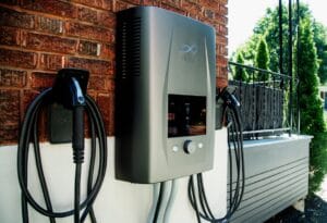
At Black Rhino Electric, we specialize in essential EV charger installations, hot tub wiring, panel replacements, and comprehensive whole home or business wiring services throughout Weber County, with expert coverage in Ogden and surrounding Utah areas. Whether you’re a business manager in Roy needing urgent panel replacements to prevent outages or a property owner in Ogden undertaking full rewiring for modern efficiency, our expert team delivers tailored solutions with precision and care.
Before you call the job finished, perform these final checks:
- Verify all tools are removed from the panel.
- Ensure all wire terminations are tight and no “stray strands” are visible.
- Test the system through three complete cycles of operation.
- Update the schematics with any changes made during the repair.
- Clean or replace the intake filters.
You know what? Keeping your facility running smoothly doesn’t have to be a mystery when you have the right experts on your side. If you need help with breakers and panels or a complete system overhaul, contact us today at 801-810-4292 or Request a Free Quote.